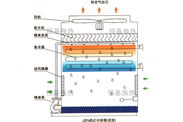
The working fluid (soft water or other liquid) circulates in the coils of a counter current closed cooling tower, and the heat of the fluid is transferred through the pipe wall, forming saturated humidity steam with water and air. The heat is discharged into the atmosphere by the fan, and the moisture is blocked and sprayed back into the water tank for circulation. During the circulation process, the spray water is cooled down by PVC fins, forming a reverse flow of wind and water with fresh air.
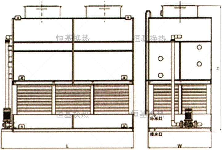
The reverse tower structure is compact, saving space, and the spray water and air flow in reverse, resulting in a large heat transfer temperature difference or enthalpy difference, which is beneficial for improving heat transfer performance. The water tray can be accessed from all sides. The open design makes the water tray easy to clean.
JBN countercurrent closed cooling tower has high performance. This cooling tower is equipped with multiple fans, which effectively suppresses noise levels and results in ultra-low noise. Also, due to the correction of the square layout of the product into a rectangle, it is greatly convenient for transportation. A closed cooling tower with a capacity of no more than 150 cubic meters and a planned width of less than 3 meters can be assembled in the factory and transported to the site by flatbed trucks.
Note: This product is used in large-scale projects and can adopt a parallel cooling system with multiple towers. If there is a large temperature difference in fluid cooling, a cross flow tower or counter flow tower series cooling system can be selected.
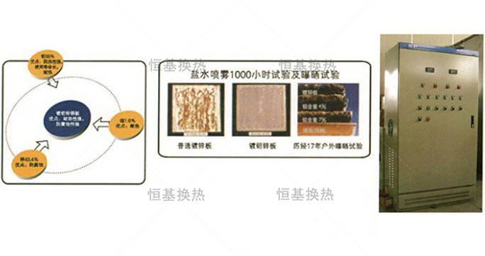
Adopting super aluminum zinc coated steel plate
The product shell is made of super aluminum zinc coated steel plate, which has a service life 3-6 times that of ordinary aluminum zinc coated steel plate, and has the advantages of strong heat resistance, excellent heat resistance, and beautiful appearance.
JBN Introduction to the characteristics of series counter current closed cooling towers
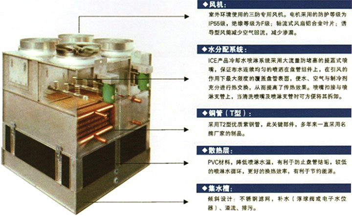
The JBN series side inlet tower features dual inlet air flow and spray water flow in the same direction. The lower part of the cooling coil is equipped with heat dissipation fins, which effectively prevent scaling on the outer wall of the coil. Additionally, the cooling efficiency is high, making it particularly suitable for high-temperature fluid cooling.
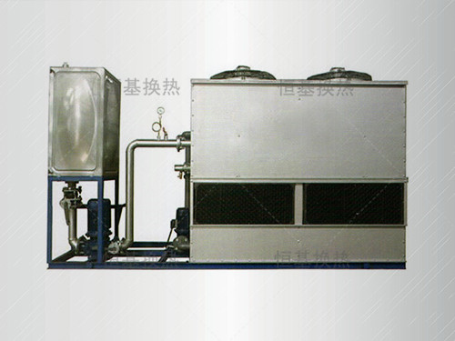
Used for fluid cooling, the product has a simple and compact structure.
Note: Depending on the requirements of process cooling water, usage environment, location, or investment strategy, this product can choose multiple structural forms and can be extended in length or width as needed. For larger cooling projects, multiple tower systems can be connected in parallel; For projects with large temperature differences, multiple tower systems can be connected in series.
JBN Standard configuration table for series counter current closed cooling tower
|
model |
cooling capacity
kcal/h |
in and out
caliber
|
sprinkler pump |
fan |
Overall dimensions
Length x Width x Height
|
empty aircraft
quality
Kg |
run
quality
Kg |
|
kw |
M3/h |
kw |
M3/h |
|
JBN-0 |
31100 |
DN50 |
0.75 |
11 |
1.1 |
12000 |
1250×1000×1900 |
390 |
700 |
|
JBN-02 |
48000 |
DN50 |
0.75 |
11 |
1.1 |
12000 |
1250×1000×1900 |
410 |
720 |
|
JBN-03 |
75000 |
DN65 |
1.1 |
22 |
0.75×2 |
24000 |
1600×1000×1900 |
560 |
1060 |
|
JBN-04 |
110000 |
DN65 |
1.1 |
22 |
0.75×2 |
24000 |
2000×1000×1900 |
700 |
1200 |
|
JBN-05 |
150000 |
DN65 |
1.5 |
25 |
1.1×2 |
33600 |
2500×1250×2100 |
770 |
1750 |
|
JBN-06 |
180000 |
DN65 |
1.5 |
25 |
1.1×2 |
33600 |
2500×1250×2100 |
865 |
1850 |
|
JBN-07 |
225000 |
DN80 |
1.1 |
45 |
1.5×2 |
33600 |
2500×1250×2700 |
1500 |
3700 |
|
JBN-08 |
260000 |
DN80 |
1.1 |
45 |
1.5×2 |
44000 |
2500×1250×2700 |
1580 |
3780 |
|
JBN-09 |
300000 |
DN80 |
1.5 |
60 |
1.5×2 |
44000 |
2500×1500×2700 |
1660 |
3860 |
|
JBN-10 |
350000 |
DN100 |
1.5 |
60 |
1.5×2 |
44000 |
2500×1500×2700 |
1900 |
4100 |
|
JBN-12 |
400000 |
DN100 |
1.5 |
65 |
2.2×2 |
69200 |
2500×1500×3290 |
1980 |
4180 |
|
JBN-13 |
450000 |
DN100 |
1.5 |
86 |
2.2×2 |
69200 |
2500×1500×3290 |
2060 |
4260 |
|
JBN-14 |
500000 |
DN100 |
2.2 |
86 |
3×2 |
69200 |
3000×1800×3290 |
2200 |
5000 |
|
JBN-15 |
550000 |
DN100 |
2.2 |
86 |
3×2 |
69200 |
3000×1800×3290 |
2480 |
5080 |
|
JBN-17 |
650000 |
DN125 |
3 |
120 |
4×2 |
69200 |
3000×2000×3290 |
2780 |
6080 |
|
JBN-19 |
750000 |
DN125 |
3 |
120 |
4×2 |
132000 |
3000×2000×3290 |
3000 |
6200 |
|
JBN-21 |
900000 |
DN150 |
4 |
150 |
5.5×2 |
132000 |
4000×2000×4200 |
3280 |
7880 |
|
JBN-22 |
1000000 |
DN150 |
4 |
150 |
5.5×2 |
132000 |
4000×2000×4200 |
3500 |
7960 |
|
JBN-24 |
1200000 |
DN200 |
4 |
180 |
7.5×2 |
200000 |
4800×2300×4500 |
3900 |
8700 |
|
JBN-25 |
1300000 |
DN200 |
4 |
180 |
7.5×2 |
200000 |
4800×2300×4500 |
4200 |
8800 |
|
JBN-26 |
1400000 |
DN200 |
5.5 |
230 |
7.5×2 |
200000 |
5400×3000×4500 |
5000 |
9800 |
|
JBN-27 |
1500000 |
DN200 |
5.5 |
230 |
7.5×2 |
200000 |
5400×3000×4500 |
5000 |
9800 |
|
JBN-28 |
1700000 |
DN250 |
5.5 |
230 |
7.5×2 |
200000 |
5400×3000×4500 |
5300 |
11900 |
|
JBN-30 |
2000000 |
DN250 |
4×2 |
360 |
11×2 |
250000 |
6000×3000×4500 |
5500 |
12300 |
|
JBN-32 |
2100000 |
DN250 |
4×2 |
360 |
11×2 |
250000 |
6000×3000×4500 |
5860 |
13000 |
|
JBN-34 |
2500000 |
DN250 |
4×2 |
360 |
11×2 |
250000 |
6000×3000×4900 |
6025 |
14600 |
|
JBN-36 |
2800000 |
DN250 |
5.5×2 |
445 |
11×2 |
250000 |
6200×3200×5500 |
7000 |
17100 |
|
JBN-38 |
3000000 |
DN300 |
5.5×2 |
445 |
11×2 |
250000 |
6200×3200×5500 |
7000 |
17100 |
Note: Technical Specifications may change with product updates without prior notice
Non standard products can be ordered according to customer needs
This parameter is the design parameter under standard conditions (wet bulb 28 ℃, temperature drop: 37 ℃ -32 ℃)
closed circuit cooling tower working principle
Air cooling section: The working fluid (soft water or other liquid) circulates in the coils of a closed cross flow cooling tower. After the fluid heat is absorbed by the tube walls of the coils, it is discharged outside the cooler through the fan on the upper side of the cooler. Characteristics: Flow direction of wind (from top to bottom and then upward through the side): The wind enters from the air inlet on the upper side of the coil cooler, then flows through the coil cooler to absorb heat, and then flows from the lower part of the cooler through the side to the air above the cooling tower.
Water cooling part: When the fluid temperature is too high (exceeding the set temperature), the spray system automatically starts, and the spray pump sprays water on the wet and hot pipe wall to form a water film, which absorbs a large amount of heat through evaporation (latent heat of evaporation). Part of the sprayed water turns into water vapor, which is carried away by the flowing air. The unevaporated water droplets drop onto the heat exchange layer of the packing and cool down before being collected in the water collection tank for the next cycle of use. The fluid in the coil is circulated in a closed manner, theoretically with no consumption.
Characteristics: Flow direction of spray water (from top to bottom): Spray water is sprayed out from the spray pipe on the upper part of the coil cooler, and then flows through the coil cooler to absorb heat before dripping into the cooling tower collection tank for the next cycle of use.
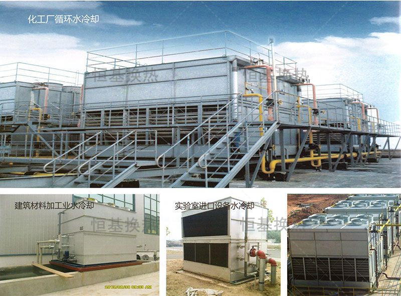
Engineering Case


 139 0618 6561